PIM (CIB) Power integrated module (converter inverter brake)
Structure
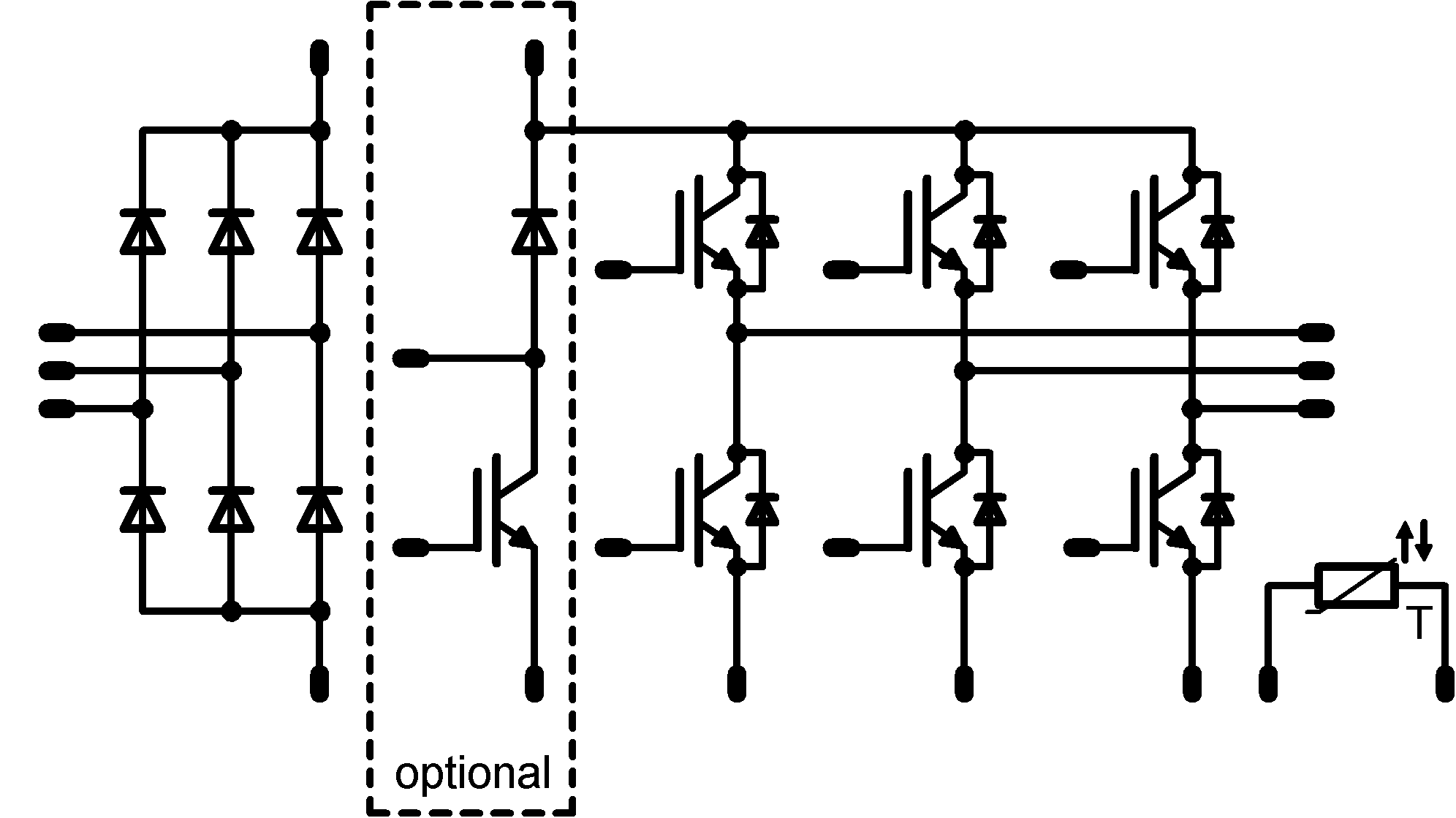
A CIB module has three functional blocks, a converter, an inverter and a brake. The converter is a rectifier with four or six diodes. Usually, 50 Hz diodes with 800 V or 1600 V blocking voltage are used to this end. The inverter consists of six IGBTs and six free-wheeling diodes. The types vary according to the given voltage: 600 V types are used for 230 V applications and 1200 V types for 400 V applications. Often, the brake chopper is also integrated together with a free-wheeling diode. The two components will have the same voltage rating as the inverter in which they are installed. Nearly all modules are equipped with an NTC or PTC alongside the power semiconductors.
Application
Power modules with CIB topology are most commonly used for drive applications. A distinction is made between normal frequency converters and servo inverters.
How it works
The rectifier converts the alternating voltage from the mains into DC voltage. A capacitor in an intermediate circuit smoothes out the pulsating DC voltage so the inverter can convert it into a variable voltage with variable frequency, which then serves to adjust electric motors' speed and torque.
The simplest way of controlling the six IGBTs is to use pulse width modulation. The switching frequency often varies from 4 kHz to 12 kHz. It can range up to 16 kHz in some cases, but switching frequencies above 16 kHz are very rare. If too much energy feeds back into the intermediate circuit—for example, because the motor is braking hard—this voltage can be limited by the chopper IGBT and an additional resistor.