Sevenpack
Structure
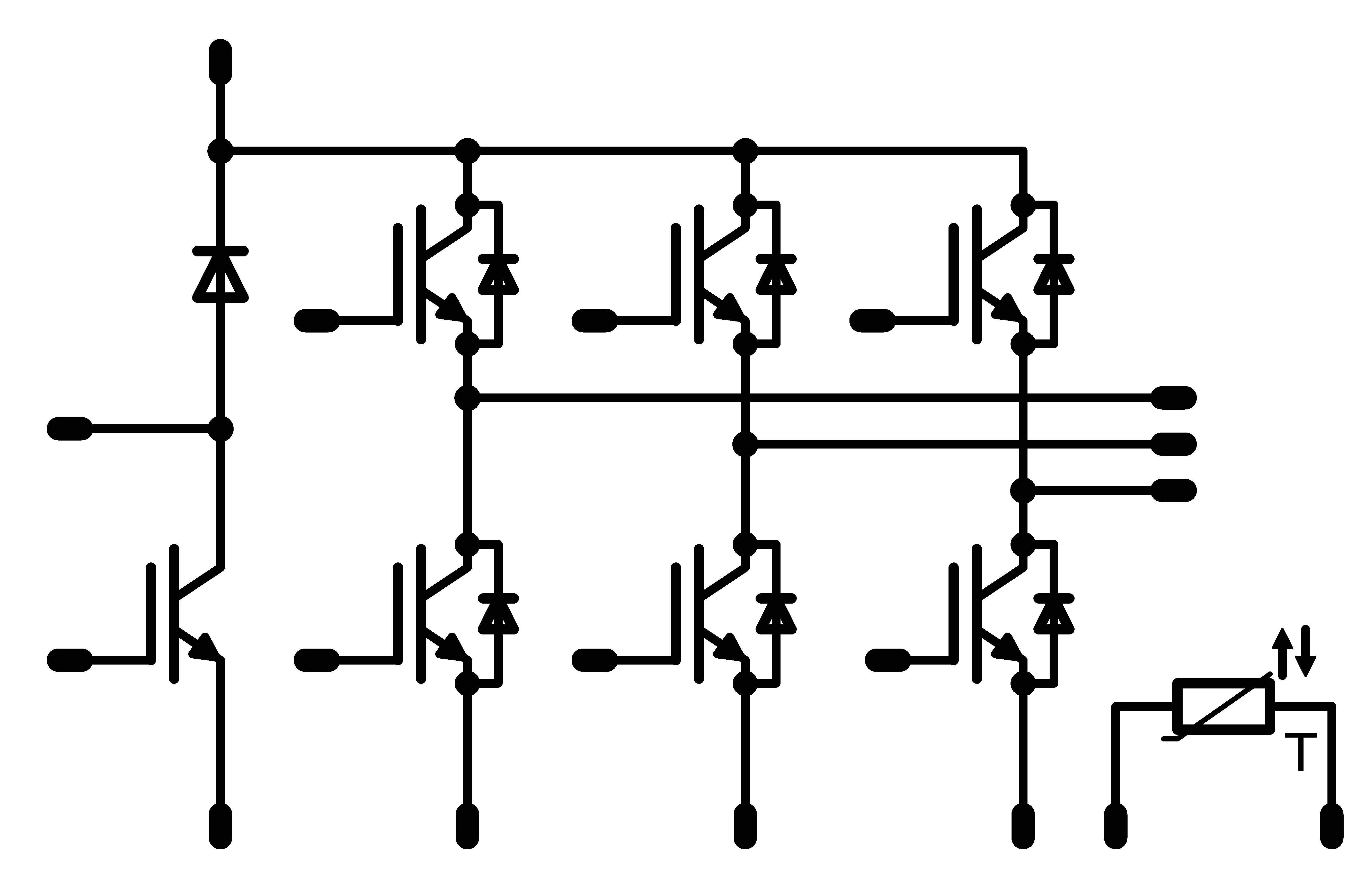
A sevenpack module features a three-phase inverter bridge and a braking chopper. The inverter is equipped with six IGBTs and six free-wheeling diodes, which usually have 600 V, 1200 V or 1700 V blocking voltage capability. The IGBTs and diodes often share the same current rating. In some modules the DC- connections are not connected together; leaving space for shunt measurement. Nearly all modules are equipped with an NTC or PTC alongside the power semiconductors.
Application
Power modules with a sevenpack topology are most frequently used in variable frequency converters for motors.
How it works
The six IGBTs convert the DC voltage into an alternating voltage by means of a PWM (pulse width modulation) signal to adjust electric motors' speed and torque. The load on the IGBTs and diodes is not the same, depending on the output voltage: the higher the output voltage, the greater the load on the IGBTs. The switching frequency often varies from 4 kHz to 12 kHz. It can range up to 16 kHz in some cases, but switching frequencies above 16 kHz are very rare.
The braking chopper limits the DC bus voltage by feeding the braking energy to a resistor where it is converted to heat.
To learn more and see the full range of products, follow this link: Sevenpack