Rectifier
Structure
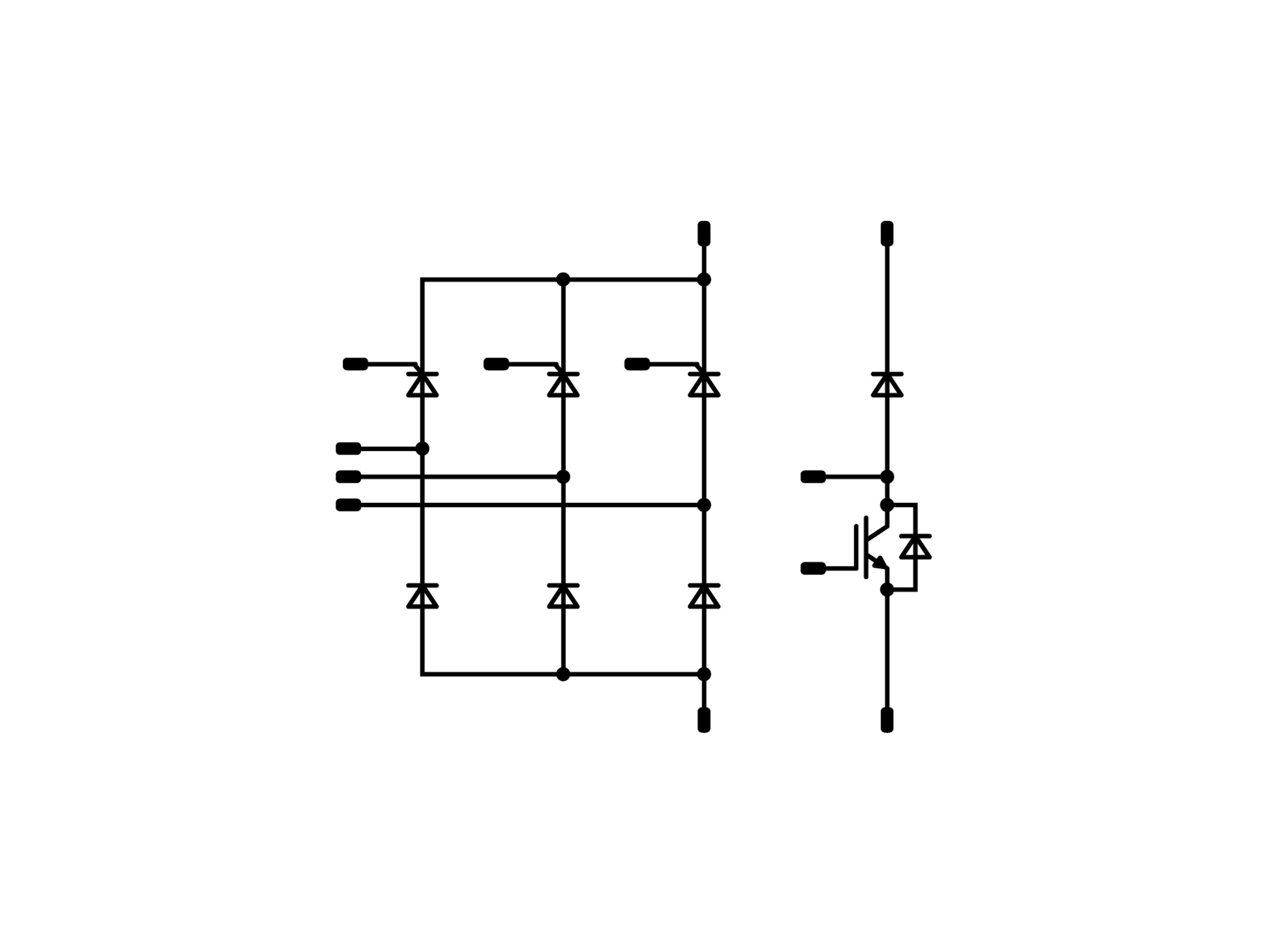
A rectifier module is equipped with four or six diodes with a blocking voltage of 800 V or 1600 V, and either three thyristors and three diodes, depending on the application. A brake chopper is also assembled in some modules. Nearly all modules are equipped with an NTC or PTC alongside the power semiconductors.
Application
Rectifier modules are often used in frequency inverters and power supplies but also in transformer based applications on the secondary side.
How it works
Mains voltage must first be converted into a DC voltage to generate a variable output voltage and output frequency. This task is carried out by a rectifier. Four rectifier diodes are required for this in single-phase applications, and six in three-phase applications. These are usually 50 or 60 Hz diodes.
A fast-switching diode is used when a high-frequency signal is to be rectified. A high charging current flows through the diodes into the DC-link capacitor when the frequency inverter switches on. The charge current can be limited using a half-controlled rectifier module with thyristors for phase-controlled modulation.
A brake chopper is optionally available in some modules. It does things like converting the braking energy emanating from the electric drive into heat. The brake chopper is usually operated at lower switching frequencies than the downstream inverter. The switching frequency is generally below 8 kHz, depending on the application.
To learn more and see the full range of products, follow this link: Rectifier