Switched reluctance motor drives
Switched reluctance motor (SRM), also called variable-reluctance motor, is gaining much interest in industrial applications such as wind energy systems and electric vehicles due to its simple and rugged construction, high‐speed operation ability, insensitivity to high temperature, and its features of fault tolerance.
SRM motors have been used extensively in clocks and phonograph turntables before, but nowadays, with the rising emphasis on energy efficiency, SR motors are taking more prominent roles in appliances, industrial uses, and commercial and vehicular applications.
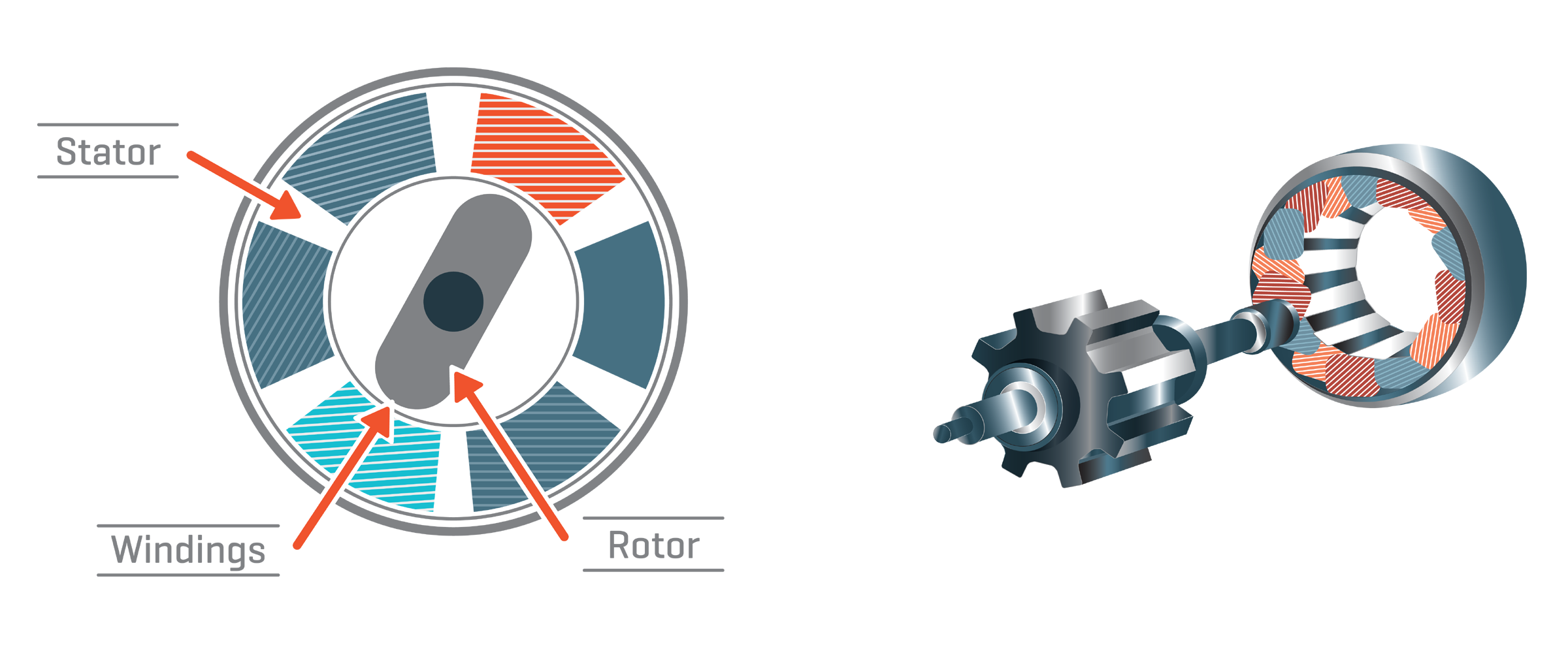
The switched reluctance motor is a low-cost electric motor that runs by reluctance torque. Power is delivered to windings in the stator (case) rather than the rotor. This greatly simplifies mechanical design as power does not have to be delivered to a moving part, but it complicates the electrical design as some sort of switching system needs to be used to deliver power to the different windings.
Switched reluctance motor manufacturers claim they offer better performance and reliability, higher efficiency, and lower price than standard induction or other adjustable speed motors.
It operates by switching currents in the stator windings in response to changes in the magnetic circuit formed by the rotor and stator. The stator of a switched reluctance motor contains windings, similar to a brushless DC motor, but the rotor is simply made of steel that is shaped into salient poles, with no windings or magnets. This is the main difference with induction motors which have rotor windings or permanent magnets. Unlike induction motors, there are no rotor bars and consequently no torque-producing current flow in the rotor in SRMs. Switched Reluctance Motors can provide an effective alternative to induction motors in many situations where the operating conditions do not suit them.
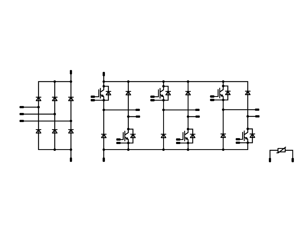
The most common approach to powering an SRM is to use an asymmetric bridge converter. The switching frequency can be 10 times lower than for AC motors.
The phases in an asymmetric bridge converter correspond to the motor phases. If both of the power switches on either side of the phase are turned on, then that corresponding phase is actuated. Once the current has risen above the set value, the switch turns off. The energy now stored within the winding maintains the current in the same direction, the so-called back EMF (BEMF). This BEMF is fed back through the diodes to the capacitor for re-use, thus improving efficiency.